In Solvix, three tabs of the model tree dictate the workflow in this software:
- Geometry – geometry editing and mesh generation,
- FEM Model – analysis set up (pre-processing),
- Results – post-processing.
Each tab also activates proper menus in the top toolbar.
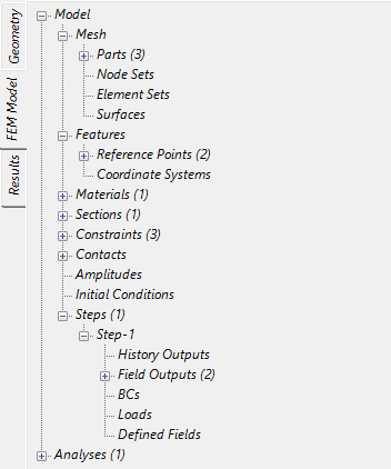
Figure 2: Solvix Model Tabs
The general steps that should be followed when working in Solvix are listed below:
- Create a new model ( File > New ) and select a model space and unit system.
- Import CAD/STL geometry or mesh for the analysis ( File > Import ). For 2D analyses, parts must be imported as faces lying entirely in the XY plane. Moreover, for axisymmetric analyses, faces representing parts must lie to the right of the Y axis. Yellow triangle with white exclamation mark next to the part’s name indicates potential issues with geometry that may require further investigation and repair (in CAD software before importing to Solvix).
- For CAD and STL geometry prepare mesh setup ( Mesh > Mesh Setup Item > Create ) and generate a mesh ( Mesh > Create Mesh ). The mesh can also be generated with no setup items – it will use default settings.
- When the mesh is successfully created, proceed to the FEM Model part of the model tree.
- Define material for the analysis ( Materials > Create ), add proper material behaviors: Elasticity, Density (for performing a modal analysis or using gravity or centrifugal loads), Plasticity (to account for permanent deformations), Thermal or Slip wear.
- Create a new section with the material defined before ( Section > Create ). Section type can be Solid (for using 3D or 2D solid elements), Shell (for using shell elements) or Membrane (for using membrane elements). The thickness must also be specified if shell, membrane or plane stress/strain elements are used. Select the part to assign the section to it.
- Create a new analysis step. Default step settings are sufficient in most cases.
- Optional: create constraints ( Constraints > Create ), define contact (expand Contact container, select Surface Interactions > Create and then select Contact pairs > Create ), initial conditions ( Initial condition > Create ), defined fields ( Define fields > Create ) and/or amplitudes ( Amplitude > Create ).
- Define boundary conditions ( BCs > Create ) and loads ( Loads > Create ). There are several types available, and they can be applied to the model in different ways (discussed later).
- Submit the analysis ( Analysis-1 > Run ), when it finishes, the results can be viewed ( Analysis-1 > Results ). Various post-processing options will be explained later.
In Solvix, it’s possible to work using node and element sets, as well as surfaces. They can be defined before any boundary condition, load, constraint or contact is created and then referenced in the definition of the selected feature. However, it’s usually preferred to add features without creating sets/surfaces first. In such cases, the selection tool within the feature window will let the user pick entities based on geometry or mesh, depending on the type of feature.
There are two main ways to work in Solvix – use options available in menus (menu bar and top toolbar) or select them in the model tree. Some more advanced options can be accessed only from the menu bar.
View controls in Solvix:
- Zoom: mouse scroll;
- Rotate model: middle mouse button or keyboard arrows;
- Pan (move model): Shift + middle mouse button.
Pressing middle mouse button anywhere on the part moves that location to the center of the screen and sets it as rotation center.
For selection, use the left mouse button (drag the mouse to use the selection box – only items entirely inside the box are selected). Holding Shift when selecting adds entities while holding Ctrl removes them.
A search bar is available on top of each of the three main tabs. It can be used to filter geometry, FEM Model and results trees.
Input fields that use units support their conversion. The user can enter a value, edit the displayed default unit (for example change MPa to GPa) and the conversion will be done after pressing Enter Solvix will display the value in default units.
In the case of failure (when Solvix suddenly closes), the user is asked if a crash recovery file should be used to regenerate the previous session.
Solvix supports post-processing of analyses with some features that are not yet implemented for pre-processing in GUI – namely, sensitivity analyses and simulations involving state variables (SDV) can be visualized.

Figure 3: Solvix Main Toolbar
File Menu #
The File menu contains the following options:
- New ( Ctrl + N ) – create a new model. The model space can be 3D, 2D Plane Stress, 2D Plane Strain or 2D Axisymmetric. The following unit systems are available (derived units are listed when a unit system is selected):
- Unitless,
- m, kg, s, °C – standard SI units,
- mm, ton, s, °C – unit set typical for mechanical engineering,
- m, ton, s, °C,
- in, lbf · s 2/in, s, °F – imperial units.
- Open ( Ctrl + O ) – open a previously created model (.svx), history (.svxh), Solvix results (.frd) or OpenFOAM files (.foam)
- Open Recent – open one of the recently used models or clear the list of the recent files.
- Run History Files – run a .svxh file.
- Import ( Ctrl + I ) – import CAD geometry, mesh or model saved in one of the following formats:
- STEP: .stp and .step (recommended in most cases),
- IGES: .igs and .iges,
- B-rep: .brep,
- Stereolitography: .stl,
- Universal: .unv,
- Netgen: .vol,
- Abaqus/Solvix input files: .inp,
- Mmg mesh: .mesh.
- Save ( Ctrl + S ) – save changes in the current model.
- Save As – save the model as .svx file with a given name.
- Export – export part/model in one of the following formats:
- STEP: .stp,
- B-rep: .brep,
- Stereolitography: .stl,
- Solvix input file: .inp,
- Abaqus input file (experimental): .inp,
- Mmg mesh: .mesh,
- Deformed mesh: .inp (respects the current deformation scale factor, exports solid elements if output is set to 3D for analysis with shell elements),
- Deformed visualization: .stl (respects the current deformation scale factor).
- Close Current Result – close the currently displayed results from the post-processing part of the model tree (saving the .svx model without the results reduces the file size).
- Close All Results – close all the results from the post-processing part of the model tree (saving the svx model without the results reduces the file size).
- Exit ( Ctrl + F4 ) – close Solvix (the user will be asked if the model should be saved first).
Edit Menu #
The Edit menu contains the following options:
- Undo – undo the last action.
- Redo – redo the action that was undone previously.
- Edit History – open history editor, making it possible to view the history of performed operations and delete the selected command entries by choosing the first column of the row and pressing the Delete key. The entire history can be deleted using the Clear All button. Changing the history will change the Regenerate functionality, so it should be used cautiously. Clearing a very long history might help with the responsiveness of Solvix since the history is saved to a file after each new command is added to it (i.e. after each feature is added to the model).
- Regenerate Model – regenerate the model (only model commands – commands for analysis and post-processing are not regenerated).
- Regenerate Model Using Other Files – swap the model’s geometry with a similar one from another file so that it is not necessary to redefine the model (only model commands – commands for analysis and post-processing are not regenerated).
- Regenerate Model With Re-meshing – re-mesh the model while keeping all the node sets, element sets and surface data defined using mesh-based selections – the model can be re-meshed without the need to redefine the geometry-based selections (only model commands – commands for analysis and post-processing are not regenerated).
- Regenerate All – regenerate the model (all commands).
- Regenerate All Using Other Files – swap the model’s geometry with a similar one from another file so that it is not necessary to redefine the model (all commands).
- Regenerate All With Re-meshing – re-mesh the model while keeping all the node sets, element sets and surface data defined using mesh-based selections – the model can be re-meshed without the need to redefine the geometry-based selections (all commands).
View Menu #
The View menu contains the following options:
- Standard Views – apply one of the predefined views:
- Front or Back,
- Top or Bottom,
- Left or Right,
- Normal, – Vertical,
- Isometric.
- Zoom to Fit – zoom the model in such a way that it fits in the window.
- Wireframe – apply a view showing only model edges.
- Show Element Edges – apply a view showing the model with the finite element edges.
- Show Model Edges – apply a view showing the model and its feature edges.
- No Edges – apply a view showing the model with no edges.
- Section View – cut the model using a plane defined by a point and a normal or disable the section view (this option can be used in post-processing as well) – warning: even solid parts appear hollow when using the section view in the Geometry tab.
- Exploded View – show assembly parts in an exploded view – 2 methods available:
- Default: Exploded view direction, Magnification, Scale factor,
- Center point: X/Y/Z coordinates, Exploded view direction, Magnification, Scale factor.
- Show All – show (unhide) all parts of the model.
- Hide All – hide all parts of the model.
- Invert Visible Parts – invert the visibility of parts.
- Undeformed – show undeformed model in results.
- Deformed – show deformed model in results.
- Deformed With Color Contours – show deformed model with contour plot in results.
- Deformed & Color & Wireframe – show deformed model with contour plot and wireframe representation of undeformed model in results.
- Deformed & Color & Solid – show deformed model with contour plot and solid representation of undeformed model in results.
- Color Annotations – use colors to distinguish items of the model based on various criteria: face orientations, parts, materials, sections, section thicknesses, all symbols, reference points, constraints, contact pairs, BCs, loads.

Figure 4: File and View toolbar
Selected options from the File and View menus can be accessed directly using a toolbar menu shown in Figure 4. This toolbar also contains two buttons for queries and annotations which will be discussed later.
Tools Menu #
The Tools menu contains the following options:
- Settings – to reset all settings in any of the tabs listed below to defaults, right-click in the empty space and select Reset all
- General
- Open last file, last file name.
- Save results in .svx files.
- Compress .svx files: No compression, Fastest, Optimal.
- Default unit system.
- Import mesh → Edge angle.
- Graphics
- Background: Type, Top color, Bottom color.
- Geometry: CAD deflection.
- Lighting: Ambient component, Diffuse component.
- Smoothing: Point smoothing, Line smoothing.
- Widgets: Coordinate system visibility, Scale widget visibility.
- Default Colors
- Face orientation: Front face color, Back face color.
- General.
- Annotations
- Design: Background type, Draw a border rectangle, Number format, Number of significant digits
- Edge/Surface annotation: Show edge/surface id, Show edge/surface type, Show edge/surface size, Show maximum value, Show minimum value, Show sum value, Show average value
- Node annotation: Show node id, Show coordinates
- Part annotation: Show part name, Show part id, Show part type, Show number of elements, Show number of nodes
- Meshing – default settings for meshing
- Mesh size: Mesh size definition, Max element factor, Min element factor, Grading,
- Elements per edge, Elements per curvature, Hausdorff factor,
- Mesh optimization: Optimize steps 2D, Optimize steps 3D,
- Mesh type: Second order, Mid-side nodes on geometry, Quad-dominated mesh,
- Mesh operations: Split compound mesh, Merge compound parts, Keep model edges.
- Pre-processing
- Color bar: Background type, Draw a border rectangle.
- Selection: Default geometry selection mode, Primary/secondary/mouse highlight color.
- Symbols: Constraint/Boundary condition/Load color, Symbol size, Node symbol size, Draw symbol edges.
- Solver
- Solver: Work directory, Use .svx folder as work directory, Executable, Default solver.
- Parallelization: Number of processors, Environment variables.
- Experimental: Convert pyramid elements to (Collapsed wedges/Collapsed hexahedrons)
- Post-processing
- Undeformed model
- Draw undeformed model: None/Wireframe body/Solid body,
- Undeformed model color.
- Limit values
- Show min value location: Yes/No,
- Show max value location: Yes/No.
- History output
- Max history output entries.
- Undeformed model
- Legend
- Color spectrum settings
- Color spectrum type: Cool-warm, Rainbow, Rainbow desaturated, Warm, Cool, Cividis, Viridis, Plasma, Black body, Inferno, KindImann, Grayscale,
- Brightness,
- Reverse colors: Yes/No,
- Number of discrete colors – in the range of 2-24.
- Color spectrum values
- Number format: Scientific/General,
- Number of significant digits – in the range of 2-8, · Min/Max limit type: Automatic/Manual.
- Design
- Background type: None/White,
- Draw a border rectangle: Yes/No.
- Color spectrum settings
- Status Block
- Design
- Status block visibility: Yes/No,
- Background type: None/White,
- Draw a border rectangle: On/Off.
- Design
- Parameters
- Name
- Value/Equation
- Evaluates to
- Query
- Vertex/Node – check the vertex/node ID, coordinates and the value of the currently displayed field output in this node (in Results).
- Facet/Element – check the facet/element ID.
- Edge – check the edge ID and its length as well as maximum, minimum and total value of the currently displayed field output along this edge (in Results).
- Surface – check the surface ID and its area as well as maximum, minimum and total value of the currently displayed field output on this surface (in Results)
- Part – check part information (name, id, type, number of elements and nodes).
- Assembly – check the number of parts, elements and nodes.
- Bounding box size – check the size of the model bounding box.
- Distance – measure the distance between two nodes.
- Angle – measure the angle using three points.
- Circle – measure the radius of the circle passing through three selected points.
- Find
- Item type: Vertex/Node, Facet/Element, Edge, Surface, Part.
- Data: Add annotation, Item id.
Currently, most of the annotations created using the Query menu display output not only in the message area at the bottom of the Solvix window but also in the form of labels attached to the model. Right clicking on them shows the options to Edit (manually change the displayed content), Reset and Delete them. This way it is also possible to access the settings menu where annotations can be further adjusted. Clicking the Clear button at the bottom of the Query window, deletes all the visible annotations (it is possible to display several annotations of different type at the same time). There is also a Remove annotations button on the File and View toolbar (Figure 6). Next to it, there is a Query button a shortcut for Tools Query . Moreover, annotations are saved in .svx files.
The Find tool can be used to locate (highlight) geometric and mesh entities with a specified ID. It can be useful for example when looking for nodes or elements reported as problematic by the solver.
Unitless parameters can be defined and then used in equations for reference point, material, section, constraint, load and boundary condition definitions. To add an equation, one should start the entry field with the equal sign = and delete the unit from the field. The equations use the open-source Ncalc library and thus its functions are supported.