The Model menu contains the following options:
Edit #
- Name,
- Model space:
- for 3D models: 3D,
- for 2D models: 2D plane stress, 2D plane strain or 2D axisymmetric,
- Model type:
- General model,
- Submodel:
- Global results .frd,
- Slip wear model:
- Results: All/Slip wear steps/Last increment of slip wear steps/Last increment of last slip wear step,
- Number of cycles – number of slip wear cycles,
- Cycles increment – increment of slip wear cycles,
- Wear smoothing steps – number of slip wear smoothing steps,
- BDM re-meshing: On/Off – enabling boundary displacement method for re-meshing due to the applied surface wear displacements after each wear cycle, boundary displacement step must be used to define fixed model regions to prevent all rigid body motions.
- Absolute zero – value of the absolute zero temperature used for radiation,
- Stefan-Boltzmann const – value of the Stefan-Boltzmann constant used for radiation,
- Gravitational const – value of the Newton’s gravitational constant.
Edit Solver Input Keywords #
A keyword editor that allows adding Solvix keywords which are currently unsupported by Solvix.
Tools #
- Find Model Edges By Angle (searches for the feature edges based on the angle in the imported meshes),
- Create Boundary Layer – creates a prismatic boundary layer on the surface (used in analyses with a bolt pre-tension load), the thickness of the layer can be specified, preview option is also available,
- Re-mesh Elements – re-meshes the selected shell region using specified max/min element size and max Hausdorff distance for boundaries approximation (0.01 is suitable for objects of size 1 in all directions),
- Thicken Shell Mesh – access to the Thicken Shell Mesh feature, available also as a mesh setup item,
- Split Part Mesh Using Surface – can split the selected base part region (volume mesh) into a coincident two-region mesh using a splitter surface (shell mesh) – useful in various scenarios where the CAD geometry is absent or when a fast mesh division is needed,
- Update Nodal Coordinates From File – updates nodal mesh coordinates from .inp files based on node IDs, can be used to introduce imperfections to nonlinear buckling analysis based on the scaled mode shape from linear buckling analysis (previously exported as deformed mesh to the .inp file).
Node #
- Renumber All
- Start node id.
- Merge Coincident Nodes
- Tolerance,
- Nodes to keep: Smaller ID/Larger ID.
Element #
- Renumber All
- Start element id.
- Element Quality – uses Gmsh element quality metrics, can create a set based on the specified criteria
- Quality metric: minDetJac (minimal Jacobian determinant), maxDetJac (maximal Jacobian determinant), minSJ (minimal scaled Jacobian), minSICN (minimal signed inverted condition number), minSIGE (signed inverted gradient error), gamma
(ratio of the inscribed to the circumscribed sphere radius), innerRadius (inner radius), outerRadius (outer radius), minIsotropy (minimum isotropy measure), angleShape (angle shape measure), minEdge (minimum straight edge length), maxEdge (maximum straight edge length), volume (element volume), - Highlight criteria: Smaller/Larger,
- Highlight limit,
- Minimum/Maximum/Average/Standard deviation.
- Quality metric: minDetJac (minimal Jacobian determinant), maxDetJac (maximal Jacobian determinant), minSJ (minimal scaled Jacobian), minSICN (minimal signed inverted condition number), minSIGE (signed inverted gradient error), gamma
Part #
- Edit: Name, Part type, Mesh, Element type (can be changed; in the case of axisymmetric models, plane stress elements can also be selected since Solvix supports axisymmetric + plane stress mixed models), Appearance,
- Transform: Translate, Scale, Rotate,
- Merge – assigns elements from multiple separate parts to one common part without changing the mesh,
- Hide, Show and Show Only,
- Set Color/Reset Color/Set Transparency,
- Delete.
Node set #
- Create,
- Edit: Name, Number of nodes, Center of gravity, Bounding box center,
- Duplicate,
- Delete.
Element set #
- Create,
- Edit: Name, Number of elements,
- Duplicate,
- Convert to Part – part created this way can be deleted to remove selected elements from the model,
- Delete.
Surface #
- Create,
- Edit: Name, Surface type, Region type,
- Duplicate,
- Delete.
Features #
- Reference point
- Create,
- Edit,
- Duplicate,
- Hide/Show/Show Only,
- Delete.
- Coordinate System
- Create,
- Edit,
- Duplicate,
- Hide/Show/Show Only,
- Delete.
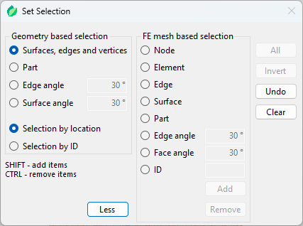
Figure 4: Set selection window
When creating sets and surfaces, a Set selection window opens (Figure 4). Sets and surfaces are named groups of nodes/elements and element faces used to define specific FEM features discussed below. Geometry based selection is more limited in terms of features, but its definition is not lost when the model is re-meshed. FE mesh based selection offers more options, but if the model is re-meshed the selection definition becomes invalid since the mesh has changed.
Two selection methods are available – by location and by ID. The first one is based on the location of the user selection (point or area). Location data is saved for when there is a need to recreate the selection (re-meshing, regenerating). If the selection is recreated the location data is used to create the selection again. The second one uses the location of the user selection to get the geometry IDs of the underlying geometry and saves only the IDs. When the selection needs to be recreated the geometry IDs are directly used again. In standard usage, like re-meshing and regenerating, those two methods are equivalent. However, if the geometry changes before re-meshing or regenerating (Regenerate Using Other Files or Swap Part Geometries), the results of the selection may change. If the topology (numbering of vertices, edges, and faces) does not change and only the geometry (dimensions) changes, the ID-based selection will always select the same vertex, edge, face of part while the location-based method might fail to do so. The ID-based method can also be used to create reference points and coordinate systems. When two or three points are supposed to be selected (selection methods Between two points and Circle center), SHIFT must be used.
Negative face angle in FE mesh based selection mode of set/surface creation can be used to select a single element face.
Surfaces can be of element type or node type. They can be also created from existing node sets. Reference points can be created using one of the following methods:
- Coordinates,
- On point – uses the Set selection window described above,
- Between two points,
- Circle center by 3 points,
- Center of gravity,
- Bounding box center.
The user can also change the color of the reference point and hide its name.
Coordinate systems (rectangular and cylindrical) can be created for use in boundary condition and load definition (so that they act in local coordinate system directions instead of the global ones). To create such a local (user) coordinate system, one needs to specify 3 points – center, point in the 1st axis direction and point on the 1-2 plane. The following selection methods can be used to define each of those points:
- Coordinates,
- On point – uses the Set selection window described above,
- Between two points,
- Circle center by 3 points.