About Geometric Non-linearites #
In Finite Element Method (FEM), geometric non-linearity occurs when a structure’s stiffness changes significantly as it deforms. This happens because the displacements, rotations, or strains are large enough to alter the component’s geometry, which in turn affects its load-bearing behavior.
In a standard linear analysis, we make a key assumption: “small displacements.” This allows us to assume the stiffness matrix \([K]\) is constant. The governing equation is the simple, linear:
\[[K]{u} = {F}\]
In a nonlinear analysis, this assumption is invalid. The stiffness itself becomes a function of the displacement, \([K(u)]\). The relationship between force and displacement is no longer a straight line.
This nonlinearity is primarily caused by two phenomena:
Large Displacements and Large Rotations #
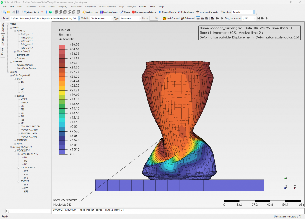
This is when a structure moves or rotates significantly, even if the material itself isn’t stretching much (i.e., strains are small). The classic example is a fishing rod or a thin-walled structure. The component’s new, deformed position changes how it resists the load. This effect is also responsible for stress stiffening, where a tensile load (like on a guitar string) increases the structure’s transverse stiffness.
Large Strains #
This occurs when the material itself is significantly stretched or deformed, such as in metal forming or rubber components. The very definition of strain must be updated to account for these large changes.
Mathematical Explanations #
The mathematical basis for geometric non-linearity lies in how we define strain and formulate the equilibrium equations.
The Nonlinear Strain-Displacement Relationship #
In linear analysis, we use the engineering strain tensor, which only includes the first-order (linear) terms of the displacement gradients.
For geometric nonlinearity, we must use a more complex definition, such as the Green-Lagrange strain tensor \((E)\). This tensor includes higher-order (quadratic) terms of the displacement gradients, which capture the nonlinear effects.
The 3D Green-Lagrange strain tensor is defined as:
\[E_{ij} = \frac{1}{2} \left( \frac{\partial u_i}{\partial X_j} + \frac{\partial u_j}{\partial X_i} + \sum_{k=1}^{3} \frac{\partial u_k}{\partial X_i} \frac{\partial u_k}{\partial X_j} \right)\]
Let’s break this down:
- \(u_i, u_j, u_k\) are the displacement components (in \(x, y, z\) ).
- \(X_i, X_j\) are the coordinates in the original, undeformed position.
- \(\underbrace{ \frac{1}{2} \left( \frac{\partial u_i}{\partial X_j} + \frac{\partial u_j}{\partial X_i} \right) }_{\text{Linear Part}}\) : This is the familiar linear engineering strain.
- \(\underbrace{ \frac{1}{2} \left( \sum_{k=1}^{3} \frac{\partial u_k}{\partial X_i} \frac{\partial u_k}{\partial X_j} \right) }_{\text{Nonlinear Part}}\): These are the quadratic terms that account for large displacements and rotations.
Because the strain definition \({E}\) is now a nonlinear (quadratic) function of the displacements \({u}\) , the resulting stiffness matrix will also be a function of \({u}\) .
The Nonlinear Equilibrium Equation #
Since the stiffness is not constant, we cannot solve \([K]{u} = {F}\) in one step. Instead, the problem must be solved iteratively, usually with an incremental load-stepping method (like the Newton-Raphson method).
We start with the governing equilibrium equation, which states that the internal forces \({F_{int}}\) must balance the external forces \({F_{ext}}\) :
\[{R} = {F_{int}(u)} – {F_{ext}} = 0\]
Where \({R}\) is the residual, or out-of-balance, force vector. The goal of the solver is to find the displacement \({u}\) that makes this residual vector zero.
To solve this iteratively, we linearize the equation at the current displacement state, which introduces the tangent stiffness matrix \([K_T]\) . This matrix represents the tangent to the force-displacement curve at the current point.
\[[K_T] {\Delta u} = {R}\]
The tangent stiffness matrix \([K_T]\) is the derivative of the internal force vector with respect to displacement. It is composed of two parts:
\[[K_T] = [K_0] + [K_G(u, \sigma)]\]
- \([K_0]\) is the standard material stiffness matrix (the same one used in linear analysis). It depends on the material properties (e.g., Young’s Modulus) and the element geometry.
- \([K_G(u, \sigma)]\) is the geometric stiffness matrix (also called the “initial stress” or “differential” stiffness matrix). This matrix explicitly accounts for the geometric non-linearity. It depends on the current displacement state \({u}\) and the resulting stress state \({\sigma}\) in the element. This is the term that captures effects like stress stiffening.
In a practical FEM solution, the solver does the following for each load step:
- Applies an increment of the external load \({F_{ext}}\) .
- Calculates the tangent stiffness \([K_T]\) based on the current state.
- Solves for an incremental displacement \({\Delta u}\).
- Updates the total displacement: \({u}_{new} = {u}_{old} + {\Delta u}\) .
- Calculates the new internal forces \({F_{int}}\) and the residual \({R}\) .
- If \({R}\) is not close to zero, it repeats steps 2-5 until the solution converges.
Total vs. Updated Lagrangian Formulations #
Finally, there are two primary frameworks for applying these equations:
- Total Lagrangian (TL): All calculations are referred back to the original, undeformed configuration. It uses the Green-Lagrange strain and the corresponding 2nd Piola-Kirchhoff stress tensor. This is common for problems with large displacements but relatively small strains (e.g., flexible beams).
- Updated Lagrangian (UL): Calculations are performed relative to the last known equilibrium configuration. The coordinate system and stiffness matrix are updated after each converged load step. This framework typically uses Cauchy (“true”) stress and is better suited for problems involving very large strains, such as metal forming.